Design and Build of a Surface Piercing Hydrofoil System
$Revision: 1.21 $$Date: 2005/08/28 13:40:22 $
Introduction
Hydrofoils are very very cool. This project will convert a conventional (1994) Moth into a hydro-foil boat with the minimum effort. The project is documented here to encourage others to try and share these or similar ideas. Contributions to this work in progress are very welcome.
Design Brief
- Cheap (Home build)
- Easy (not too much time investment)
- Fun
- Fast
- Maybe even Work!
The Ultimate Moth Hydrofoil System
I think the best systems will be electronically controlled active submerged systems. This may not be legal at the moment. (I think after the Euro 2004 meeting it is). I think it is a sensible direction to go in. Fly by wire will make the boats easy to sail and need not be too expensive. Chris Millers control system paper is a excellent piece of work that I think will be the catalyst for such systems. However active control systems, (electronic or mechanical) are ruled out of this project because the time investment to get them working properly is too large.If you want the Ultimate system now then buy it. It is very good and this project says big up and Re Spect (Alli-G style). However the beauty of the Moth class is that there is always some silly bastard with a silly idea, that sometimes works and changes the sport of sailing! (Mostly however it is just a silly bastard idea.)
The Diamond Hydrofoil System.
This is a design that I think is well worth a try. The concept is to stick a tapered surface piercing V foil on the dagger board that will require no active control system. The faster you go the higher you ride. A T foil rudder will provide longitudinal stability. The design has two Vs that form a diamond that can be glued on to the dagger board.The tactics of Hydrofoil racing mean that you have to get out of the water earlier (in less wind) than your competitors. Therefore we need bigger foils than the active systems. The drag of these big foils will be reduced once the ride height increases and the top of the diamond is out the water.
The boat will need to fly all the time to be competitive. If the wind is so light that you can not fly then the race will probably be canceled. This system will sail with the hull down but it will probably not be competitive. Only active systems that can feather foils will have a chance against conventional Moths in non foiling winds. This design may feather its foils if the sailor sits forward for a traditional bow down trim. The wind range under 7 knots will be a problem, but who wants to sail in this wind.
Ventilation (air attaching to the foils) may be a problem but we do not know until we try. I think the pressures are low so it may be OK. We can always put small ventilation barriers on the foils to help. Maybe the sailor can bounce the boat to clear the air? I think I have to solve this when it happens and not before.
The mail foil will generate most of the lift, so its of attack is critical. The deck fastening and the shape of its root need to allow it to be fastened at different angles. With sea trials it will become clear where it should be fastened and this position may vary in different wind strengths.
The rear T foil will generate lift if the sailor sits back in the boat. The forward foil may jump out of the water in this case, which may or may not be a problem. The proportions of the foils and the sailing technique will evolve. I will try to make a good first guess and develop from there. Therefore is is a waste of time to build expensive high quality foils because after the first sails the hack saw may come out. The build system must therefore be cheap and easy. Once the proportions are settled then high quality foils can be made.
When this system works we do not need much of a boat. Maybe the boat does not need to float much. In this case it can be very small and light and easy to build. Its shape and fairness will be irrelevant the important factors will be weight, strength and windage. This may mean that the expense of female molds will be consigned to history..
My conversion plan consists of a new rudder and new centerboard with a deck fastening system on the boat. I will keep my old foils in tact so that the boat can be sailed normally. Therefore the cost and risk of conversion is small and I can continue sailing my boat.
The first design will go for control to allow the boat to be driven hard. T-Foils on the rudder dramatically increased the speed of Moths not because of hydrodynamic reasons but because you could sheet in and drive the boat down wind rather than tickle it to the leeward mark. Therefore again the ultimate low drag system is to come later. What we need now is a stable system that lifts early and can be driven hard while you look up to see which way the fleet is going up the beet or where the camera boat is on the reach.
Basic Calculations
If you think these calculations and assumptions are ridicules then you are probably right, so mail me and I can include your thoughts in this project.Get out the water first.
The foil system needs to generate more lift that the competition a low speed, which means low wind. This is a bit tricky because the speed is important for lift and lift is related to drag. Therefore if we have a huge foil system we will have more drag and not go as fast as the competition. If we do not go as fast then the velocity squared thing means we should have stayed in the bar. Therefore in this critical condition we need to have more area and/or a larger angle of attack, and not too much more drag. If we can do this then we are out the water and the drag drops, speed increases, and we wave good bye.Area of competition =================== The aussie system data I have is: "Main foil is 90cm wide with a chord of 12cm The rudder is 52cm wide with the same chord." => 0.9 * 0.12 + 0.52 * 0.12 = 0.1704 sqm.This is the projected area. If we have have 45 degree foils then we need sqrt(2) 1.414 times more physical area.
Fixed foils have no flaps so the angle of attack is related to boat trim. Therefore we want to change our trim with the use of our ballast (where we sit). That means that is we sit back in the boat the main foil will ride up and increase the angle of attack of the system. We can then sit forward a bit to put pressure on the main foil and lift the boat out the water.
Assuming:
1. We can not generate as much lift coefficient (angle of attack) as active
   systems. assume 75 % of the lift coefficient.
2. We have more wetted area and more drag therefore we go 10% slower.  Which
   is 20% less lift.

SameArea = 1.2 * 0.1704 / 0.75 = 0.273
Our design area = more then present systems (because we want to get out the water first) = 0.3 msq

Therefore the submerged system should have a projected area of about 0.3 msq.
Stable Full speed
In the full speed condition the lift is the weight of the boat and sailor. The area of the submerged system is constant and the therefore the coefficient of lift is very small to compensate the velocity squared effect.At full speed (what ever that is) we need a bit of main foil in the water for stability and the aft foil must remain submerged. Ventilation is our problem so the pressure on the main foil should be low to reduce this problem. Our area is now low because most of the diamond is out of the water. The boat ideally should not jump when it hits a wave because of ventilation and control reasons. Therefore I think that the main foil should lift the boat and the rear foil should be an always submerged stabilizer. This keeps some pressure on the main foil to stop it jumping. It also means that the the rudder has more draft than the main foil to keep it wet.
Assuming:
1. Main foil generates 75% of the lift.
2. We need about a 1/4 of the area of the submerged system (that is now
   dragging huge foils around) for the same lift.
3. 1.414 times more area for the main foil is counted because it is 45 degrees
   to the water.

NeededArea = 0.1704 * 0.25 = 0.0426 msq
RearFoilArea = 0.0426 msq
At a 10cm cord that makes a ~45 cm span foil.

Going back to the "Get out the water first" case.
Main foil total projected area = 0.3 - 0.0426 = 0.2574 msq

At 45 degrees this makes a physical area of:
0.2574 * 1.414 = 0.364 msq

Starting at an 8cm cord and finishing at a 30 cm cord the foil needs to be:
( 0.08 + 0.3 ) / 2 = AverageCord = 0.19
0.364 / 0.19 = 1.916 m long
EachSideOfDiamond = 2 / 4 = 0.50

Therefore our main foil dimensions are.

Main foil Diamond.
Top of diamond cord = 30 cm
Bottom of Diamond cord = 8cm
Each side of diamond length = 50 cm
What would happen if this works?
Assuming this design works and we are out of the water and sailing lets do a reality check calculation for a sailing at 15 Knots condition.V = 15 Knots is aprox 8 m /s^2 L = Required lift = 100 KG = 1000 d = Density of water. CL = 0.2 This is a nice CL Number. L = ½ d V^2 S CL 1000 = 0.5 * 1000 * 8*8 * S * 0.2 S = 0.156 This is about half the main foils projected area. Assuming 75% of the lift comes from the Diamond. Projected area from main foil is 0.156 * 0.75 = 0.117 sqm The projected area of the lower half = 0.7 * (0.08 + 0.19) / 2 = 0.0945 Therefore at 15 Knots we would be running with the diamond about 75% submerged.The 15 knot case assumes a lot but it is realistic, so we can conclude our reality check is OK. The CL gives us a lot of room for adjustment. We can adjust the CL by raking the main foil forward. Increasing the CL may make ventilation more of a problem, but would reduce our wetter area and help us get out of the water earlier. This is a subject that is very complex but it could be examined further with maths and computer modeling. The control of the boat and its behavior can never be fully modeled, as it is far to complex. I feel is cheaper and quicker to use reality rather than virtual reality from this point forward.
My feeling is that the main foil will need to be raked forward about 3 degrees to help us get out of the water. So it is important that the mounting on the boat allows this adjustment.
The angle of attack at the top of the diamond could be more than that of the bottom. We could assume that the bottom should run level with and the top should have a small angle of attack. Our mail foil will have a flat underside to make it easy to shape and asymmetric. Therefore the bottom of the diamond could be parallel to the static water line and the top could have a slight angle of attack to make it generate loads of lift at low speed. This however means there is no chance to feather the foils at non foiling speed and it should also generate so much drag that the boat can never get out the water. Therefore the bottom of the foils will be flat and parallel to the static waterline of the boat. This also makes the build easy.
We have our basic dimensions which fit with practical considerations. We might have loads more lift than the competition at low speed so we can ride out the water first and are therefore faster. We might also have a stable hight control system at high speed so we can drive the boat harder with less wetted area in strong winds. Sounds cool but will it work? I have no idea but I think there is only one way to find out.
Drawings


Diamond Foils Sections
I will use the NACA 64 series foil section because I have data for it. I is also a nice section with the max thickness far back for good laminar flow. This also helps with the even pressure distribution required for surface percing foils, (to help prevent ventilation).To make the foils easy to build the slight concave aft will be run straight with a sanding board. I also have to adjust the section so that it is 20mm thick. This makes is too fat at the bottom and too thin at the top but easy to shape out of a 20mm thick sheet of foam.
| NACA 64-012 Section offsets and modified for 20mm thick foam. | ||||||
| Y | X | X | X | |||
| X % | Y 12% | 20mm Thick | 100mm Cord | 150mm Cord | 280mm Cord | |
| 0.00 | .000 | 0.000 | 0.000 | 0.000 | 0.000 | |
| 0.50 | .978 | 1.630 | 0.500 | 0.750 | 1.400 | |
| 0.75 | 1.179 | 1.965 | 0.750 | 1.125 | 2.100 | |
| 1.25 | 1.490 | 2.483 | 1.250 | 1.875 | 3.500 | |
| 2.25 | 2.035 | 3.392 | 2.250 | 3.375 | 6.300 | |
| 5.00 | 2.810 | 4.683 | 5.000 | 7.500 | 14.000 | |
| 7.50 | 3.394 | 5.657 | 7.500 | 11.250 | 21.000 | |
| 10.00 | 3.871 | 6.452 | 10.000 | 15.000 | 28.000 | |
| 15.00 | 4.620 | 7.700 | 15.000 | 22.500 | 42.000 | |
| 20.00 | 5.173 | 8.622 | 20.000 | 30.000 | 56.000 | |
| 25.00 | 5.576 | 9.293 | 25.000 | 37.500 | 70.000 | |
| 30.00 | 5.844 | 9.740 | 30.000 | 45.000 | 84.000 | |
| 35.00 | 5.978 | 9.963 | 35.000 | 52.500 | 98.000 | |
| 40.00 | 5.981 | 9.968 | 40.000 | 60.000 | 112.000 | |
| 45.00 | 5.798 | 9.663 | 45.000 | 67.500 | 126.000 | |
| 50.00 | 5.480 | 9.133 | 50.000 | 75.000 | 140.000 | |
| 55.00 | 5.056 | 8.427 | 55.000 | 82.500 | 154.000 | |
| 60.00 | 4.548 | 7.580 | 60.000 | 90.000 | 168.000 | |
| 65.00 | 3.974 | 6.623 | 65.000 | 97.500 | 182.000 | |
| 70.00 | 3.350 | 5.583 | 70.000 | 105.000 | 196.000 | |
| 75.00 | 2.695 | 4.492 | 75.000 | 112.500 | 210.000 | |
| 80.00 | 2.029 | 3.382 | 80.000 | 120.000 | 224.000 | |
| 85.00 | 1.382 | 2.303 | 85.000 | 127.500 | 238.000 | |
| 90.00 | .786 | 1.310 | 90.000 | 135.000 | 252.000 | |
| 95.00 | .288 | 0.480 | 95.000 | 142.500 | 266.000 | |
| 100.00 | .000 | 0.000 | 100.000 | 150.000 | 280.000 | |
Boat Fastening.
It would be of great benefit to be able to adjust the angle of rake, and therefore the angle attack, of the diamond foil. This can be done with a pivot on the underside of the hull and a simple control system in the boat. I rope and jammer system to tie the top of the main foil back (and therefore rake forward) will be enough.
Build Design
Foils are to be shaped out of high density foam and covered in one layer of UD and one layer of cloth. More layers of UD to be added where needed.Due to the fact that the Diamond is effectively a fully supported beam and only 50cm long I will same some money an use Glass fiber for this not Carbon.
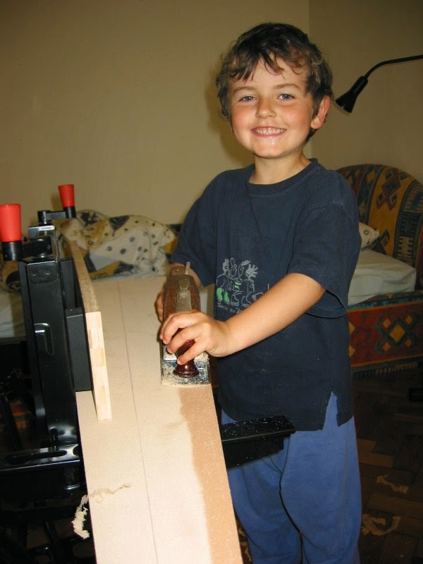
Actual Build


Sea Trials


The first sail started as the South wind came in. This meant I launched in no
wind and then the breeze increase steadily to a force 3-4. The boat behaved
just like a normal low rider but obviously was a bit slower due to the extra
wetted area of the foils. As the wind increased she started to lift on a
reach. The boat lifted better with a lower angle of attack (4 degrees). The
larger angle (8 degrees) caused too much drag and as lift is the square root of
velocity so speed not area or angle of attack are important. Therefore less
drag is much more important than I thought so smaller foils, at less angle of
attack could be better at getting the boat out of the water!?...


I decided to repair the Diamond that had failed at the junction at its top, and fit ventilation fences to the upper foil to stop the drop into the water as soon as the diamond top cleared the water.
The next sail started in a force 3 and the same drop into the water occurred. On studying the water more closely I got the impression that it was not just a ventilation stall, but a complex vortex that was being generated. This vortex was a result of the 3 foil surfaces and the water air interface. It produced a big drag that caused the boat to slow and drop and air to be sucked down into the water. As the wind increased there was enough power to get thought this vortex drag hump and start flying with the diamond behaving as a surface piercing V foil. Then the problem was ride height control I got the impression that this was mainly solvable with technique but did not get the hang of it before the next crack in the top Diamond junction got to a critical length and I had to stop. At this point I feathered the foil for safety and sailed the boat back the the shore and it behaved like a normal low rider


Conclusion
I did manage to get the Diamond nearly clear of the water and had some proper crashes from high altitudes, although I was not in control is was fun. I could also switch off the diamond and make the boat behave like a normal Moth. With development of sailing technique and the diamond dimensions a stable ride height may be possible. The drag hump problem would need to be understood better and solved as it is a speed killer and will make the design uncompetative.Cheap?
The project cost me about 600 Euro and half of this was the high density foam. Therefore if a more accurate and cheaper build technique is well worth investigating. Hot wiring cheap low density foam could half the cost of the project and produce more accurate sections. I am not sure if I achieved the cheap design requirement.Fun?
The project was a lot of fun and cost me about 100 hours of build time. Therefore I feel it was worth while, and I archived the fun requirement.Fast?
If is not easy to build a prototype that can compete with 3 years of development. The other hydrofoil boats at the front of the fleet are a lot faster. This system is not too far off working but still needs development to make it competitive with low riders. I do not think it will ever be competitive with the modern hydrofoilers. Therefore I think that it did not achieve the fast design requirement.Maybe Even Work?
For a first go a lot of things worked surprisingly well but I decided to low ride for the European Championship event as the system was not really race ready. I could have turned it of and sailed the boat as low rider and turned it on for the reaches, but I had the opportunity to race competitively against a fleet of Moths so I thought that would be more interesting. I can splash around on my own in Austria at any time. I nearly achieved the Work requirement.This project was a lot of fun and I have enjoyed it but I will put my future energy into copying the existing systems rather than developing version 2 of the diamond. Thanks a lot to everyone that helped me to do this experiment especialy Adam May that made it possible. This has been a fun project with input and interest from a lot of people and that is what the Moth class is about. This is probably the end of the Diamond story, but I hope you have enjoyed reading about it.
Discussion
Chris Miller wrote on 06.09.204:

   hi,

   read thought your paper, looks good. i tried a similar design, but instead
   of a diamond i used a V. the problem was the V was not big enough (two 40 cm
   parts). i used that length since it was what i had.

   a note on your performance evaluations, when you compare the the drag with
   the T foil type you say that the drag will be higher, i disagree.  There is
   one thing you don't take into consideration, there is drag from the
   dagger-board in the T foil design, where as the diamond design has no
   dagger-board. This means that although the drag from the vertical lifting
   surfaces is higher, they are also acting as horizontal lifting surfaces.

   The total immersed areas are similar when you include the dagger-board.
   However there is an extra surface piecing element which is hard to predict
   the drag from.

   overall i really like the design, i think people will like sailing it
   since you are using body weight position to control the fly height and
   pitch of the boat. it will be very much like trimming a current boat for
   pitch.

   i think i might go and build a set this week. carve them out of wood, then
   cover in carbon.

   chris

Doug Culnane Replied on 06.09.2004:

   I think you are right that the horizontal component is complex and needs to
   be considered.  I was thinking on the U-Bahn this morning that this design
   will work if sailed flat but the traditional heeled to windward state may
   be a disaster.  However this stuff is so experimental that I think it needs
   to be tested to find out what the real problems are.  Unfortunately my
   boat is in the UK so I can not test it until the Europeans at Garda.  If
   you do test it send me pictures and your thoughts.

   Thanks for your response

   Doug

Adam May wrote on 07.09.2004

   Hi there Doug. Interesting stuff. The really scary thing is that I think it
   might just work!

    A few points though: (I know you've made compromises according to your
    brief, but I'll come at it from the Olympic prep angle and we'll meet in the
    middle!)

    I was worried that windward performance would be poor. The conventional (if
    you can call them that) foilers are not good upwind when first foiling, but
    in more breeze heel to windward and utilise some of the foil lift to help
    against leeway, thus achieving good tacking angles in a breeze. You will
    need to be careful to always stay upright in order to achieve some element
    of ride height adjustment. But on pondering this further, I've found you
    actually run very consistent speed upwind, and very little wand or tiller
    movement is required. I think your system could heel to windward, and you
    would just have a course, one or two foils in the water lifting system. Body
    movement, steering, and sheeting would probably be okay. Certainly Graham
    Vials was fine upwind with Linton's first experimental set of foils. He had
    no adjustment on the rudder foil, just a big flap on the main foil, but the
    linkage wasn't very good, so it didn't move much anyway. He could just sail
    it upwind fine on body movement alone.

    My main foil was one of the largest, and a more average main foil size is :
    85cm / 80cm. 1st in the Euros was 80cm, 2nd 85cm and 3rd, 90cm..... John
    Ilet is looking at doing all further foil sets at sizes of 85cm main foil
    and 65cm rudder (spans).

    Rudder and gantry loads are huge - do not underestimate!

    The current foilers are very stable once flying, but they have got a 80cm
    main foil, and 50/60cm rudder foil help dampen the roll. I'm worried you
    will not be as stable once up at speed. I'd be tempted to start with an over
    span rudder foil to possibly help with this early on, and then cut down from
    there.

    The relative angle of main lifting foil to rudder foil is quite crucial, and
    an element of adjustability there would help. Possibly not practical for
    you, but my gantry is bolted on and I have a few different sizes of wedges
    that I use under the bottom support to fine tune the rudder foil angle
    relative to the main foil. Currently I'm getting too much lift, and have to
    sit a long way back. I'll try and measure the angles, and then we can figure
    out the differences, and get yours close first time!

    The main centreboard vertical element can be much smaller in chord. The Ilet
    ones went to a 12cm chord because the boat was getting blown over it once up
    using a normal size foil.

    Once up does it fall into the multihull issue that Brett Burvills boat had?
    A silly point I know but the class needs to encourage foilers of all sorts
    and a general acceptance of all concepts should be sort. The class doesn't
    seem to worry about the wand system but I wouldn't be surprised if the rules
    thing gets brought up at some point. I think we should allow any configs
    though!

    The more I think about it, the more I think this could actually work. Good
    on ya!

    I'll read it again, and if I come up with anything else I'll give you a
    shout.

    Adam

Doug Culnane Replied on 07.09.2004:

    Dear Adam,

    Thanks for your response it is very encouraging, and interesting.

    I have been thinking more about this design and I think the diamond needs
    to be a symmetrical section and run very neutral in angle of attack.  I
    could have a pin pivot that stops the board riding up but allows it to be
    raked forward.  This would allow the foil to be feathered in non-foiling
    winds and the boat would behave like a conventional Moth with very large
    foils.  As the wind increases then a pull on a rope to rake the foil
    forward will put an angle of attack of the diamond and it will generate
    lift.  Once airborne then surface piercing properties should keep it
    stable in heave and the rudder should trail along to keep the boat level
    like a conventional T-foil rudder.  The rake control line could be
    adjusted like a kicker for wind and course changes.  This makes the
    control of the boat easier because you only have to worry about the
    tiller, mainsheet, where you sit and where the camera boat is.

    I do not know how it will handle heeled to windward or with ventilation as
    these are very complex with may factors to consider.  Maybe small angles
    of attack on the diamond will keep enough of it in the water to grip its
    way up windward, and reduce the pressure and ventilation problem.  This
    has to be tested but I really think there is a slight chance of getting
    this working the day before Garda.

    The multihull thing is a bit strange but as I understand it the wing
    mounted surface piercing foils made the boat very stable and boring to
    sail and that is why it was outlawed.  I think my system will be suitably
    tricky to sail, to stay legal.  I do however agree that I think it would
    be wise for the class to not rule out development at this stage.  However
    I also understand that we do not want to sail multihulls.

    The whole structure thing is going to be a challenge and I think a couple
    of extra layers everywhere would be a good idea at this stage.  I hear
    Garda is very deep so sinking is a bad idea.

    I do not think that the angle of attack between the rudder and diamond is
    critical.  The rudder must just keep the transom level and trail along
    like the other moths.  On your system I can imagine that it is very
    critical.  I plan to make this T foil as drawn in the hope I can cut bits
    off it.  The draw foil is very large by conventional standards and we
    hopefully are going to fly a lot faster.  So velocity squared means it is
    huge and the saw is going to come out.  However it is easier to cut off
    than stick  on.

    Thanks again for your feedback.  It is great when someone else thinks this
    will work because I am in danger of starting to believe it now myself.
    I do not think this is competition for boats fitted with your system at
    this stage but it could be good enought for conventioal Moths to be
    convered to hydrofoil boats and sail with the hydrofoil fleet.  Maybe
    someone will test it for me on their boat?

    All the best,

    Doug

Olav Arne Nehls wrote on 06.09.2004

    Dear Doug,

    Regarding your diamond foil concept: Does it look similar to Roger Angell's
    foils at the 2003 Worlds in France (see attached sketch)? Unfortunately it
    didn't work at least in the waves we had there but it may be great with an
    additional height control system.

    Regards, Olav

Doug Replied:

    Dear Olav,

    I was not aware that Rodger did this because I have not been active in the
    class for a while (8 Years)...

    What was the reason why it did not work?

    All the best,

    Doug

Olav Replied:

    In the mail you sent me last night you asked why Roger Angell's foils didn't
    work. Let me first explain how they looked:

    His hull is based on a Skippy Mk. I - same underwater sections but much less
    freeboard and no flares (I have included the 4 photos of his boat I took at
    the Worlds last year to this e-mail). It has a really large rudder blade
    with a T-foil (elliptical plan form, low aspect ratio) on a removable
    gantry. The diamond-shaped foils were fitted quite near to the hull bottom
    (Roger removed them after the first heat) as shown on the sketch I sent you
    yesterday.

    AFAIK the biggest problems were ventilation and lack of longitudinal
    stability. Probably some ventilation fences could fix this (but I have no
    experience how effective such devices are) and a longer distance between
    rudder and centreboard would be beneficial. I also think the hydrofoils were
    too small (if I remember correctly the diamond had a width of maybe
    600-700mm max.). After Roger had removed his foils he only competed in one
    more race in VERY (!!!) light conditions but even then the swell was too
    much for the low hull. I also have no idea what aerofoil sections he used,
    they probably had a too big Cl even at low speeds so the boat would have
    come out of the water too far...

    All the best,

    Olav

    Doug,

Doug Replied something along the lines of:

    Thanks for info what about your foil system?

Olav Replied on 07.09.2004:

    my foil system of course isn't top secret  :-) , I didn't even invent it
    though. As long as I'm not an expert in fluid dynamics and stuff (I have
    some little knowledge from various textbooks) it'll be some guesswork and
    experimentation. What I want to build and try out first is the following,
    based on the design by Rich Miller (www.foils.org/miller.htm):

    - Canard: My boat has some kind of a 2nd daggercase between the mast and
    stem. A canard (450*150mm, NACA 0009) on a strut will be fitted into this
    slot so it runs on the water surface like a water ski. The strut is going to
    have a free length of around 300mm below the hull which will be the design
    ride height of the flying boat. After trying this out (I want to start as
    simple as possible to get some experience - my goal is to have the minimum
    number of movable parts in the system) I'm sure I'll build a wand-controlled
    system to operate the canard as Ian Ward did.

    - Centreboard: Raked back (to increase the distance between the main lifting
    foil and the canard), 900mm long below the hull, 150mm chord, NACA 0012. The
    top of the board is 400*225mm/NACA 0012 so it fits into the centrecase.

    - Main hydrofoil: Sits at the tip of the centreboard, size is 1500*150mm and
    it features a NACA 4412 aerofoil section.

    - Rudder: Standard T-foil blade as used in displacement mode, probably with
    an adjustable T-foil or a trim tab. In foiling mode it'll be attached to a
    rigid carbon fibre outrigger (similar to the ones John Ilett manufactures,
    also see my renderings) to increase course stability.

    As I mentioned I'm sure it won't be the final arrangement but this is what I
    want to start from.

    All the best, Olav

    P.S.: Did you already read the foiler design thread on www.boatdesign.net?
    Very interesting and lots of useful information!

    P.P.S.: I use the software "designFOIL" to analyze different foil sections.
    It includes a virtual wind tunnel, you can add flaps to the section and see
    what happens.

    You can download a trial version from www.designfoil.com The only thing is
    that you can only save 5 times if you want to design your own sections but
    it can generate the most common NACA 4- and 5-digit sections. I use to
    export them to SolidWorks but if you have Rhino it's good as well - and
    exporting them isn't regarded as saving.


PHIL STEVENSON wrote on 08.09.2004:

    Doug,
    Saw your memo on pommy discussion site which lead me to your diamond foil
    page.

    Thought I might help with some of my experience.

    Last summer I tried a main foil with turned up tips, about 1200 total span
    with the last 400 each side bent up at around 40 degrees. The section was
    a hand shaped assymetrical foil, probably higher camber than Illets' NACA
    section.

    Down wind it had plenty of lift and I suffered many breakout crashes at
    pretty good speed. But upwind it was an absolute dog, lucky to beat a
    scow.

    My theory is that the leeway angle at which the boat sails upwind, changes
    the AOA of the sloping foils by such a large angle that one is much higher
    than optimum and the other is much lower. I have done no calculations.

    This might be OK maybe with symetrical section foils but was a disaster
    with mine. So be wary and do some calculations with leway angles included.

    I then cut off the tips and bonded them on with slight dihedral at span of
    about 700. With these I got similar performance downwind and good upwind
    speed without hull flying. Still plenty of downwind crashes though.

    This season I have an Illet foil with wand. Only one sail so far and some
    tuning required to get it flying at the right height.

    I also have a fin raking system working.  So I can change the main foil
    AOA instead of adjusting a rudder foil flap.

    Phil Stevenson
    AUS9324
    Sydney

Doug Replied:

    Dear Phil,

    Thanks very much for your input.  I was originally planning asymmetrical
    foils for the diamond but I think this will generate opposing horizontal
    lifts that do nothing but increase drag.  Therefore with my resent
    discussions I am coming round to the idea of a symmetrical system that
    rakes forward to generate lift.  Therefore it is very interesting to hear
    you confirm the idea of symmetrical foils.

    I posted the mail to the pomy list but I will do something similar to the
    German and Australian list soon because the discussion is very useful and
    interesting, and I think there are a lot of sailors like me that want to
    get flying easily and cheaply.  I hope to contact Wardi because this
    project is right up his street.

    Do you have some pictures of your foils for my collection.

    Thanks again,

    Doug

Olav Arne Nehls wrote on 08.09.2004:

    Hi Doug,

    Your diamond foil concept sounds really interesting and I agree with your
    basic calculations. Do you have a certain foil section in mind yet?

    I'm still a bit in doubt with my NACA 4412. IMHO on a foiling sailboat it's
    necessary to have an aerofoil section with a quite high Cl for low take-off
    speeds, a good Cl/Cd ratio, forgiving stall characteristics, and ? very
    important! - a ?stable? Cl that doesn't increase too violently at even
    little changes of AOA so the boat doesn't jump out of the water just because
    you may have moved some millimetres too far back. Does such a section exist
    at all???

    Another factor to consider according to Ian Ward's experience is the
    (negative) pitching moment an asymmetrical section produces. I guess the
    main job of the rudder T-foil then is to prevent the boat tripping over its
    nose, i.e. producing slightly negative lift so the main foil probably has to
    carry the whole load instead of just 75%. Am I wrong?

    Looking forward to new thoughts!

    All the best, Olav

Doug Replied:

    I will spend some U-Bahn time thinking about the foil construction thing.

    CNC is too expensive if you do not have free access to the gear.  Female
    molds are to much work for one off builds.  The hot wire method is very
    good because you can use the cut out scrap to clamp down the laminate
    while the resin dries.  This makes a hight quality lamination as well as
    fast accurate shaping.  A hotter hot wire may be worth trying....

    I think my design is not developed enough to worry about sections.   I
    have ruled out asymmetric (see discussion) and so that leaves the classic
    NACA rudder sections in my eyes.

    Perhaps others have ideas they can contribute to the discussion

    I think that where you sit in the Diamond design determines the lift
    distribution.  The system should be very pitch stable (if it works).  The
    only danger is that the diamond gets negative lift so it has to be raked
    forward when flying and not be in danger of swinging back or the boat with
    trip and stop and at 25 knots that could hurt.  The hydro dynamic pitching
    moments of the foils I would say are insignificant compared to the pitching
    moment the sail has.

    All the best,

    Doug

Mike Ewart wrote on 9.11.2004:

    Read with great interest your design brief and the comments, on the point
    of upwind work surely the use of symmetrical foils will give the effect of
    a centre board as they are at 45 degrees the same effective area in the
    vertical and the horizontal plane, and the purpose of symmetrical foils
    as per tee foil on the rudder is to resist change, thus they are now going
    to give the effect of a c/b and a lift foil?

Doug Replied:

    Dear Mike,

    Thank you for your message.  I have been thinking a lot about how to
    analyze the foil system.  It is easy to calculate the lift and drag on
    foils but at 45 degrees I am not so sure.  My model uses is a mathematical
    box around the diamond.  These projected areas are the sides of the box.
    Then you can calculate the forces in the planes we are interested in.  I
    think this model is accurate enough but am can not prove it, only discuss
    it.  There may well be studies out there that use the same approach but I
    have not searched.

    This system design I think is good enough to work and deserves to be tried,
    because if it does work then you are right the foils give the same effect
    of a centerboard and rudder and also lift the boat out the water.  It is
    easy to fit the system to a conventional boat and has no complex wand
    control system, therefore it fits my brief.

    Others seam to have tried something similar but I think their foils were
    too small.  Phil also make what I think is a mistake and one that I
    initially made and that is to make the foils sections asymmetrical.  This
    turns in the sides of the mathematical box so that the sides generate
    opposing lifts and drag.  I also think that if the diamond pivots and can
    be adjusted then really could work around the course.

    I am afraid I have fallen in to the trap of starting to take this
    seriously, and really believe its going to work!

    All the best,

    Doug

Mike Ewart Replied:

   Dear Doug

   agree with you there is some good stuff about foils and effective area of
   inclined foils in "High Speed Sailing" and they make no mention of what
   plane they are referring too, I think it might work as well and am very
   tempted, I have been playing with some ideas based around a conventional
   hull shape with angled foils that retract into a recess in the hull, and
   looking at a system with a scow type hull with curved centre boards but
   yours is cheaper and simpler.

   regards Mike Ewart


Doug Replied:

    Dear Mike,

    A system that retracts into the hull may well be a lot better that the
    Diamond system, but it will be complicated and expensive to fit, and take
    time to get it to work.  Good luck and please send me detail and pictures
    of any system you try weather it works or not, because I think there are
    a lot of Want to Flyers out there like me who are very interested.

    All the best,

    Doug

Olav Arne Nehls wrote on 22.09.2004:

    I recently found very interesting instructions on how to make a power device
    for cutting styrofoam with a hot wire:
    http://www.nsrca.org/technical/tip_tricks/foam_cutter/foam_cutting_power_supply.htm

    May be of interest for you?

    Olav

Doug Replied on 1.10.2004:

    Thanks for the link it is very interesting.  There is definitely something
    to learn about foil building from the model makers....

    I think though that it is too complex for me at this stage.  I think I will
    get some high density foam and shape it with woodworking tools.

    Doug


Simon Propper posted to the UK List on 1.10.2004:

    For all you DIY foil makers

    I found this site in the US where you can order foam blanks cut to your own
    profile. May be of use?

    http://www.compufoamcore.com/

    Good luck

    Simon

Doug Replyed to list:

    Thanks for the link.  I think that shaping foam with wood-working tools is
    very old fashioned and that this kind of service is very interesting.   I
    do however feel that my 2" plane is going to get used waxed up because I
    am an old fashioned guy.  Sooner or later this old dog will have to learn
    some new tricks.

    Has anyone else built foils without using a 2" plane?

    Doug Culnane

Chris Miller wrote on 08.10.2004:

    hi,

    i've developed a simple mathematical mode of your diamond design. All you
    have to do is choose a takeoff speed and fly height and max speed (whatever
    that is!). It produces a tapered twisted blade. Its only hand written at
    the moment so i cant send it to you, but I'll type it up and forward you
    a copy.

    To summarise it, twisting the foils has the same affect as taper and
    immersion depth, so lift is a function of fly height (well of immersion
    depth) by way of a cubic,

        ie L = ax3 + bx2 + cx

    where x is the foil immersion depth and a, b and c are constants defined
    by two parameters, the taper and twist ratios and the angle of attack and
    chord of the tip.

    I think this is a very desirable characteristic for the system.

    chris

Doug Replied:

    Dear Chris,

    Very Cool idea Chris but:

    What happens when the winds are light and the Diamond is fully immersed?
    You have a twisted foil that you can not feather to run at zero lift.
    This means big big drag.  (Maybe?)

    However twisting the foil is a good idea to help with the "lift is a
    function of fly height (well of immersion depth) by way of a cubic"
    thing.

    I originally I thought in terms of asymmetrical foils and having a larger
    angle of attach on the upper foil but I went away from the idea, because
    I think it is cooler to be able to feather the foils in light winds.  If
    you can build a case for the Diamond that allows it to be raked forwards
    when the wind picks up out on the water you can say OK let see if she will
    fly and rake the board forward to get lots of lift and out of the water.
    As the wind increases she may be riding too high and the pressure on the
    Diamond may mean that it is ventilating all the time.  You can then reduce
    the angle of attach to keep more of the diamond in the water and have more
    control.  (Maybe?)

    I do not know if I am right but I think a straight foil is worth a try
    first and it is a lot easier to build.  You may well be right and small
    amounts of twist may be useful to refine the design later, because I
    totally agree that "I think this is a very desirable characteristic for
    the system."

    All the best and thanks a lot for your input,

    Doug

Chris Replied,

    hey,

    I wasn't really designing the system for non-foiling, but you are right to
    consider it. i also considered having a speed sensor or wand to alter the
    diamond angle (all mechanical). However it may be easier to do it manually.

    The twisted foil produces a much drag as a larger foil (twist equivalent
    to taper - i think!). Just out of interest what would be the minimum speed
    for a moth? i.e. how fast does it go in say a force 1 or 2?

    another think you could do with twist and taper would be to design the
    system so it self damped, but i don't know how to do this yet - i think
    that's well hard core. lets get it flying first!

    chris

Doug Replied:

    I did not start this design with the non foiling in mind either but it
    occurred to me that it could be considered, and not written off with some
    stupid comment about "Who wants to sail in light winds anyway" (quote Doug
    Culnane).

    I did not  think of a wand sensor controlling the diamond angle that is
    VERY interesting and something to think about.....

    Doug

Chris Miller wrote:

    hey

    see below, i've added comments to your points

    On 9 Oct 2004, at 13:33, Doug Culnane wrote:


    >> I think you could be right Chris but it is a long time since I did my
    >> 2 dimensional foil theory.   I think that there is a CD (surface drag)
    >> part and induced (related to lift) drag part, and you have to add the
    >> two together.  This is going back 10 years...  Maybe Adam can remember
    >> he studied airplanes 8 years ago and has drunk a lot less beer so his
    >> brain may work better.  If he can not remember I could dig my books
    >> out but I would have to remember where I put them...


    Yep your right, there is a surface drag component, but i don't know how
    to model it. i never did that at uni! may need to read up on it. the
    induced drag component comes from the hight pressure fluid on the lower
    surface of the foil wanting to go round the end of the foil to the low
    pressure high side. the creates a vortex of the foil tips. However the
    diamond foil does not have ends, so the only extra drag will be from
    the surface piecing.


    >>
    >> It did occur to me that a little lift in light winds could be
    >> beneficial but I thought that I should design a system that did not
    >> have negative lift and test to see what the best position for the foil
    >> rake was.  I expect this to vary in different wind strengths.
    >> Therefore the idea of being able to have no lift or lots of lift by
    >> the pull of a string makes the design very flexible (and therefore
    >> more likely to work).  No lift is also good when the rudder breaks and
    >> and you do not want to Type D all the way home.


    Yep, an adjustable foil angle i think will be very important for fine
    tuning the system, and maybe as another control. You have to remember
    that you get about 5 degrees adjustment by varying the angle of the
    boat. i''m not quite sure how the diamond foil interacts with the T
    foil rudder, does the rudder contribute any lift, or is it set a zero
    so it simply stabilises?


    >>
    >> I am sure that this is complex and when the real world problems like
    >> "remembering to sheet in to force the bow down when the boat get too
    >> hi...?!!  will not make it more simple to understand.  My theory and
    >> mathematical modeling is crude and we could study this in a more
    >> mature way (if someone  measured accurate speed data of existing
    >> systems) but this is very complex and a bit too hard.  I think it is
    >> easier to build cheap foils and test to see what works best, however
    >> this discussion is very nice and fun because it help me understand all
    >> the details better.
    >>
    >> Your idea of a sensor and actuator is very interesting and could make
    >> the system much much more heave stable, (which is the biggest problem
    >> with the other systems)  I do not have the option of developing a wand
    >> system because my system has to work out of the box.  I may well try
    >> this out next winter.  I am very interested in the details of your
    >> experiments.


    Some sort of heave velocity sensor could be employed, for example a
    small vane that aligns itself to the flow direction. When the flow is
    going up or down the foil this vane could actuate a small control flap
    or something like that. This could also be done on the fastacraft foils
    that would make the craft much more heave stable. It would be in effect
    adding differential control, such the D in PID control (proportion,
    integral, differential).

    However the foils currently do this already to a certain extent, due to
    when the foils move up or down through the water you get an apparent
    flow effect (such as you get apparent wind while sailing downwind). The
    larger area the diamond design has will increase this affect.

    Do we really want sensors and the like on the foils? its only adding
    cost and complication to the design. It would be better to avoid active
    systems if we can.


    >>
    >> I thought I would study the videos of the Australian surface piercing
    >> Moth which seamed to work very well, until one foil ventilates and
    >> that side drops.  The sizes of it foils are in the same ball park as
    >> the Diamond and so I think it is good evidence that a surface piercing
    >> system could work if the headache of ventilation can be overcome.  At
    >> least the Diamond has more chance of dropping level when it does
    >> ventilate.
    >>


    Each foil was 0.5m long, which gives your design twice as much surface
    area. Also with twisted tapered foils huge amounts of lift should be
    available in comparison. The biggest problem wind rush was waves.
    Sailing downwind when one foil was on the crest and the other in a
    trough caused the boat to be very unstable. The diamond design should
    be much better due the foils being closer together (windrush's foils
    were wing tip mounted).


    >> All the best,
    >>
    >> Doug
    >>


    chris

Doug Posted to the UK Moth List:

    Dear Moth sailors that may be interested in hydrofoil design calculations
    and what I can not really remember,

    I could not find my books but I looked at my Moth design paper which does
    not display the formulas correctly but I think I am correct when saying
    there are two components of drag when calculating wing performance.

    Component of Drag from the section:
    Profile drag is related to the section shape and how it performs at angles
    of attack.  (This is what people get over interested in but basically every
    smooth foil is the same.  Some smooth foils do behave slightly differently
    to others.)  This is very important if you are designing the next Boeing
    747 that will have to carry some large foils around for a billion miles and
    each mile costs expensive fuel.  A 0.02% increase in performance vs. drag
    will be worth spending $50,000 on research to get.  However if are a low
    rider and want to be a DIY high flyer then I think that any smooth plank
    will do because the design problem is control and the fact that it must
    work at 0.01 knots of boat speed and 30? knots.  (speed squared means 0 to
    (30? x 30? =) loads and loads.)

    Component of Drag from lift:
    Induced drag is related to lift and influenced by the plan form and aspect
    ratio for the foil.  End plates like T foils and water air interfaces
    (Surface Pricing :-) ) extend the effective aspect ratio which helps.

    Therefore this is complex and not worth getting to uptight about (when is
    is more important to remember to sheet in to go down?!..)

    I think that it is true to say that you do not get something for nothing.
    You can not get lift without extra overall drag.  So in a Moth you have to
    carry your foils around in no wind and so  they should do nothing.  However
    they are good when they do something and reduce the wetted area of the hull
    or better still, get the thing out the water completely and also reduce
    wave drag as well as wetted area drag.

    I love the expression "Low Rider" it sounds cool and if the diamond foil
    works I will call it the "Easy Rider".  If it does not work I will call it
    the "**** Rider".  However anything is better than a "No Rider".

    Doug Culnane
    Low Rider GBR 4019

Tom Edom wrote on 21.10.2004:

    Doug and other DIY foilers,

    You may know about this but... at Boatdesign.net there is an
    extensive thread on dinghy foiler design. Many but not all are moth
    related with lots of input from Wardi, the Stevos, Andy P and Rohan.
    There  are also some very perceptive technical inputs from Tom Speer
    and some others (see his website at www.tspeer.com) .  There are
    about 12 pages to the thread and wading through it is almost as good
    as reading a book about dinghy foilers (if there was one). The URL is
    http://www.boatdesign.net/forums/forumdisplay.php?f=12 and look for
    Foiler Design.  If you want to air your design you will get an
    international peer review!

    Cheers
    Tom Edom GBR 4064


Doug posted to the UK List on 17.11.2004:

    I recently spent a week in the UK on holiday from Austria and took the
    opportunity to visit Adam May and take him up on the offer of a go in his
    boat.  This is a brain dump of my thoughts and experience, with respect to
    trying to DIY fly.  I welcome feedback and discussion.  I would class my
    self as a  reasonable  Moth sailor from the middle of the fleet.  I have
    not sailed a Moth or any other high performance boat for 7 years, so I am
    a bit out of practice, but  I think my first time experience will be
    representative for most experienced Moth sailors.


    Day One:

    I had great luck that the wind in Weymouth was a steady 10 Knots on flat
    water.  This was enough to fly but in the lulls it was low riding
    conditions.  I got the odd gentle gust to give me a taste of how the boat
    may behave in stronger winds.  This is probably the optimum first fly wind.

    Launching looked a very wet, cold and uncomfortable activity so it was good
    that Adam could do this alone. After a quick sailing demonstration Adam
    landed the windward wing on the pontoon and stepped out allowing me to step
    in.  This was very civilized because swimming in November is not my idea
    of fun.

    I quickly remembered what sailing a Moth was like and that it aint that
    easy.  The boat was slow upwind and lifting a bit, but felt like a draggy
    low rider.   I could not really fly it upwind in these marginal foiling
    conditions but I think unfortunately this was due to bad technique.  The
    boat seamed very unstable and I put this down to the high angle of the
    wings on Adams boat.  It had to go a long way before a wing hit the water
    and provided some roll damping.

    I tried a bit of reaching and the boat flew nicely, but it was clear that
    there was a lot going on.  Maintaining flying hight is very complex.  I
    decided to set and forget the rudder trim tab because it was more trouble
    than it was worth.  The mechanism is a bit clunky and you have to remember
    which way to turn it.   The rudder and mainsheet have a large effect on the
    pitch of the boat, and therefore the heave.  I started to re-learn how to
    use them to control pitch and heave with the forward drive of the sail.
    This was something that was clearly going to take a few flying hours to
    get right.  The wand did not seam to be any help at all, and dragged
    thought the water most of the time.

    I had one nice little gust when broad reached and hiking off the wing bar.
    After the initial fright from the acceleration. The boat climbed high and
    would not go back down.  I was waiting for the boat to do a ventilation
    drop and concentrating to try and work out which type it would be (A, B ,C,
    D, E....)  I then realized that the wand was working and controlling the
    ride hight.  I was riding high up in the air and the wand was bouncing
    along the surface.  There were no waves and so it was easy.  After a few
    seconds I started to relax and enjoy the experience (and look for the
    camera boat).  My GPS top speed reading of 14.4 knots what probably at
    this point.  Adams 17.2 Knots reading in the same wind shows how boat
    handling is the key to control and control is the key to speed.

    I tried a few gibes on foils for fun and could only laugh at how weirded
    it was. Again there was a lot to learn to get this right.

    I managed to deliver the windward wing back to the pontoon and stepped out
    so that Adam could step in and swim the boat into the beach.  I had escaped
    the first day with no capsizes and no swims.  I had a lot of information to
    process and had the feeling that sailing in a force 3 could be a great deal
    of challenging fun and also that I was back on a very steep learning curve
    which is my favorite place to be.  The flap controls worked but had lots of
    development potential.  The overriding factor when competing with other
    boats will be boat handling and that flying time is essential, fun and very
    very fast.


    Day Two:

    The next day was windy.  I estimate that there was a good force 4.  After a
    pint of lunch time bravery juice I was ready to have a go.

    It was clear that we both needed to swim to get the boat launched.  I made
    the beginners mistake of going to the leeward wing (where it was shallower
    and therefore a little warmer) to hold the boat while Adam boarded it.
    Adam sheeted in and the leeward wing forced me under the water, and then
    I was reminded that there are other foils under the water by a painful rap
    on the angles from the main foils.  Adam said that he was not trying to
    drown me on purpose but I am not so sure.  At this point I realized that
    today my body, and ego was going to get a bashing.

    Adam handed over by capsizing near the pontoon and I swam out to right the
    boat.  I sailed up wind gently and under control.  I then boar off to see
    if I could get back downwind.  The answer was a clear NO FUCKING WAY.

    I did not have the confidence (or stupidity) to sheet in and drive the boat
    hard so I tried to nurse it downwind but there was no way this thing was
    going to play nice.  The boat would ride up on the foils and then it was
    either going to to fall into a broach or capsize.  The wings hit the water
    before the hull and so it was very hard to recover from these crash
    landings.

    After a short wrestle I decided that a win would equate to getting the boat
    and myself back to the beach in one piece.  My fitness meant that I had a
    limited amount to energy and time to get the boat in and a near miss with a
    concrete jetty confirmed that there was no chance of a rest.  I was very
    relived to get the boat close enough to the pontoon to shout SWIM at Adam.

    Adam then showed me how the professional do it. My jaw dropped when he
    drove the boat into a gibe forced the boom across because the apparent
    wind strength meant the gibe was technically a tack.  It all look very
    impressive until as he tried to get his balance on the new gibe and pressed
    the ejector seat button by accident. He bounced 4 foot in the air out the
    back of the boat over the transom.  On the second attempt he fell across
    the boat head first as it capsized at about 8 knots......

    I am not saying that sailing these boats are impossible to sail in strong
    winds, but it is not easy and it can only be done well with lots of
    determined practice.  There is a lot happening and you need to understand
    a lot of new dynamic stability factors and how they interact, because this
    is a very exciting new dimension to sailing.  If you remember the
    excitement and challenge of sailing your new narrow low rider (with no
    T-foil rudder) in a force 5 for the first time, then double it and you got
    a foiler in a force 4.


    Random Conclusions:

    - The idiots that talk about having a top speed to brag about should shut
      up because it is scary out there and the trick is slowing the thing down
      as the wind increases.
    - You got to be fit and on the ball to make a reasonable job of flying.
      The action never stops. There is always something going on and there is
      no physical or mental rest from the time you take the sail out the bag
      until you get it rolled up again.
    - If you can not get the boat off the beach and are having trouble launching
      then you probably should not be out a sea.
    - Simon Payne says that the boat is alway talking to you.  This is total
      rubbish.  The thing is screaming it head of, you have to learn to manage
      a state of information overload.
    - Sailing Wizkids beware:  Unless you can get round the cans in a force 5
      in a low rider, you can not jump out of your 4*0, B*, RS* or R2D2 and
      expect to fly a Moth.  Moth sailing is hard.  Flying Moths is Fucking
      hard.
    - When you get your new shiny foiler be careful who takes it for a joy
      ride, because these thing are not Laser dinghies..
    - The KA McSail is very like a wind surfer sail.  It has an On - Off type
      of trim.   It is either generating loads of low drag power or a stalled
      out rag of crap.  There is a learning curve to get the most out of the
      modern sails and they are not forgiving.
    - The Moth class has a challenge to get new sailors good enough and
      determined enough to sail these boats.  Being the hardest boat to sail
      is good and will alway attract the best sailors, but retaining the best
      sailors attention is hard.  No Flying Moth sailor will want to sail a
      Laser but not many Laser sailors will want to go thought the ego bash of
      a Moth. Narrow Moths started this effect and I see that the hydrofoils
      will exaggerate it.  I think that the class has to be careful that the
      middle and lower third of the fleet are not left behind.  But maybe this
      is crap because I am a middle of the fleet sailor that has been
      encouraged back to the fleet by these developments.
    - Lintons female molded foils were very impressive and well made but I was
      not worried too much about the section and build quality of the foils while
      I was trying to get back to safety in a force 4. I think we are still in a
      pioneering period where concept, control system and rider skill is more
      important that build quality.
    - I used to be able to sail my low rider around the cans in 30 Knots of
      brease.  I would like to see the video of a top fliers getting to the
      leeward mark in that wind.
    - Talking to Adam about Lesson videos the camera boat can destroy your boat
      if they get too close so you need a big bay an no one chasing you if you
      are flying.  These boats stop very fast and unpredictably so you have to
      make sure you have got a landing slot and you need to protect it.  (When
      you find out were the camera boat is tell him to piss off).


    Thanks:

    - Big thanks to Adam for trusting me with his boat, and for swimming to my
      rescue.
    - Thanks to Linton for showing me round his workshop and providing boat
      launching facilities.
    - Thanks to Alison and Colin for the hospitalityInt-Moth_UK@yahoogroups.com
      and traditional English Chinese.


    What effect does this have on the Diamond foil project?

    Life is too short not to be involved in this exciting game and I want to
    Fly more than ever.  The Fast Foil / Full Force  (4F) system is very well
    developed and the thing basically works very well, but it is not easy to
    sail well.  The top sailors will be refining these systems and working on
    boat handling.  I think that you can not compete with these guys unless
    you spend a great deal of time flying.

    I plan to turn up and fly around lake Garda at the Europeans with an
    untested home build system and no practice.  Since Garda is a traditionally
    windy location this is a rather stupid plan, but a good opportunity to test
    a new concept and have a laugh.  Therefore I still plan to build the
    diamond design and take it to Garda.

    One feature of the diamond design is that it can be potentially turned off
    by feathering the foils. This could be its most important feature when I
    have to make the decision weather to use it for the event after the first
    few test sails.

    The latest plan is that Adam will make the center board box arrangement
    that fits to the boat and post it to me.  I will glue a diamond to it and
    make a rudder.  The foils will be shaped out of pine and covered in loads
    of UD carbon.  My next task is to go to Ikea and buy a few wooden shelfs
    and shape them into foils.

    All the best,

    Doug


    Hey,


Chris posted to the UK List on 11.12.2004:

    I've put some stuff about a simulation I've done on the diamond foil.
    http://www.intmoth.f2s.com/theory/diamond.html

    chris

Doug Replied:

    Very interesting Chris.
    Did you model a FastCraft type system as well.  I think that it would be
    interesting to compare the two systems.

    I also think that it would be interesting to run the simulations with
    different foil configurations to find out what the effect of a large main
    foil is or what happens as the rudder T foil gets smaller.  This is all
    very theoretical but I think it may be good enough to help us understand
    the control effects of the many different factors.  I do not pretend to
    understand control system as well as you but I would have thought that
    this modeling should be targeted to be able to make control conclusions
    like.  Big main foils are easier to sail but slower for example.

    Doug

Lyndon Beasley wrote on 21.01.2005:

    I am following your foiler development with interest, would like to
    have a dabble at making some if I ever get the time. How big would I
    need to get a Magnum7 airborne?

Doug Replied:

    I have no idea how big the foils should be. But a clearer answer would
    be "I would say that the mag 7 is 10 to 20 kg heavier (~15% more total
    weight) so make the foils 15 % bigger."  However I have no idea if the
    dimensions of the original design are good.

    I have cut out my diamond plan form blank.  It is a diagonal cut through
    an Ikea Traggen? ( pine shelf cost 6.99 EUR :-) ).

    My carefully calculated dimensions are:
    30cm cord at the top of the diamond.
    ~9cm cord at the bottom and the diamond.
    The diamond is now 4 x 60cm  in length.

    This is bigger than planed but it allows me some extra length for
    mistakes...

    I now need to make some section templates.  I think I will ask  Chris
    Miller if he has some symmetrical surface piercing hydrofoil section
    data or CAD files (please Chris) to save me some work...  Once the two
    sides are shaped I have to get some carbon on them fast before the pine
    warps too much...

    I will post some pics of the Ikea catalog on the site soon for
    reference......

Chris Miller Replied:

    Hey, I'm about to start building some diamond foils too! The section you
    should use is an H105 section. It is a modern laminar flow section that also
    reduces pressure peaks over the foil. This is good for surface piercing
    foils due to cavitation being reduced. Refer to my papers section of my site
    for downloads of the paper detailing its section etc..

    http://www.intmoth.f2s.com/forum/viewtopic.php?t=20

    Its the first link on the page.

    chris

Doug Replied:

    I had a look at the section and it is exactly the kind of thing I want:

    "It is a modern laminar flow section that also reduces pressure peaks over
    the foil. This is good for surface piercing foils due to ventilation being
    reduced."

    However it is not symmetrical and I need a better quality drawing of it or
    some offset data to make a drawing.  Do you know if this exists?

    What are the dimensions of your Ikea shelf or have you got some proper
    materials?  Send me pics if you have them.


Doug Posted to the UK List on 14.04.2005

    The project is under going a reality check at the moment.  If it passes
    this test I hope to produce a prototype but I am not sure if it will
    work.  I found a better source of materials than Ikea and found CAD
    drawings of NACA sections in my /home/doug/StuffDoneAndForgotten
    directory.  I am ready to start building but before I spend cash on
    plastic... The reality check question is am I stupid enough to build
    something that may not work and costs x when I can buy something that
    does and costs y.  I hope the answer is Yes, but the cost mathematics of
    materials against lintons price list are more accurate than my foil
    theory calcs.

No comments:
Post a Comment